We spent the last year and a half designing, building, and programming a meter-tall sign of our logo. While our Sign may look heavenly, the journey to get it to completion was anything but. Now, we’re sharing our journey with you.
0: Who’s Who
First, let me introduce you to the subject of this story, the Sign:
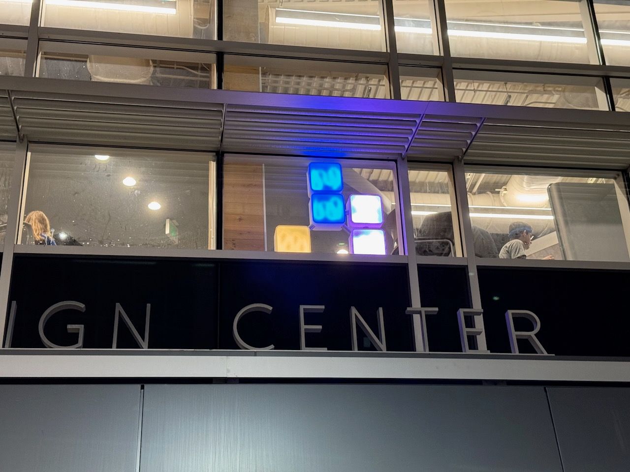
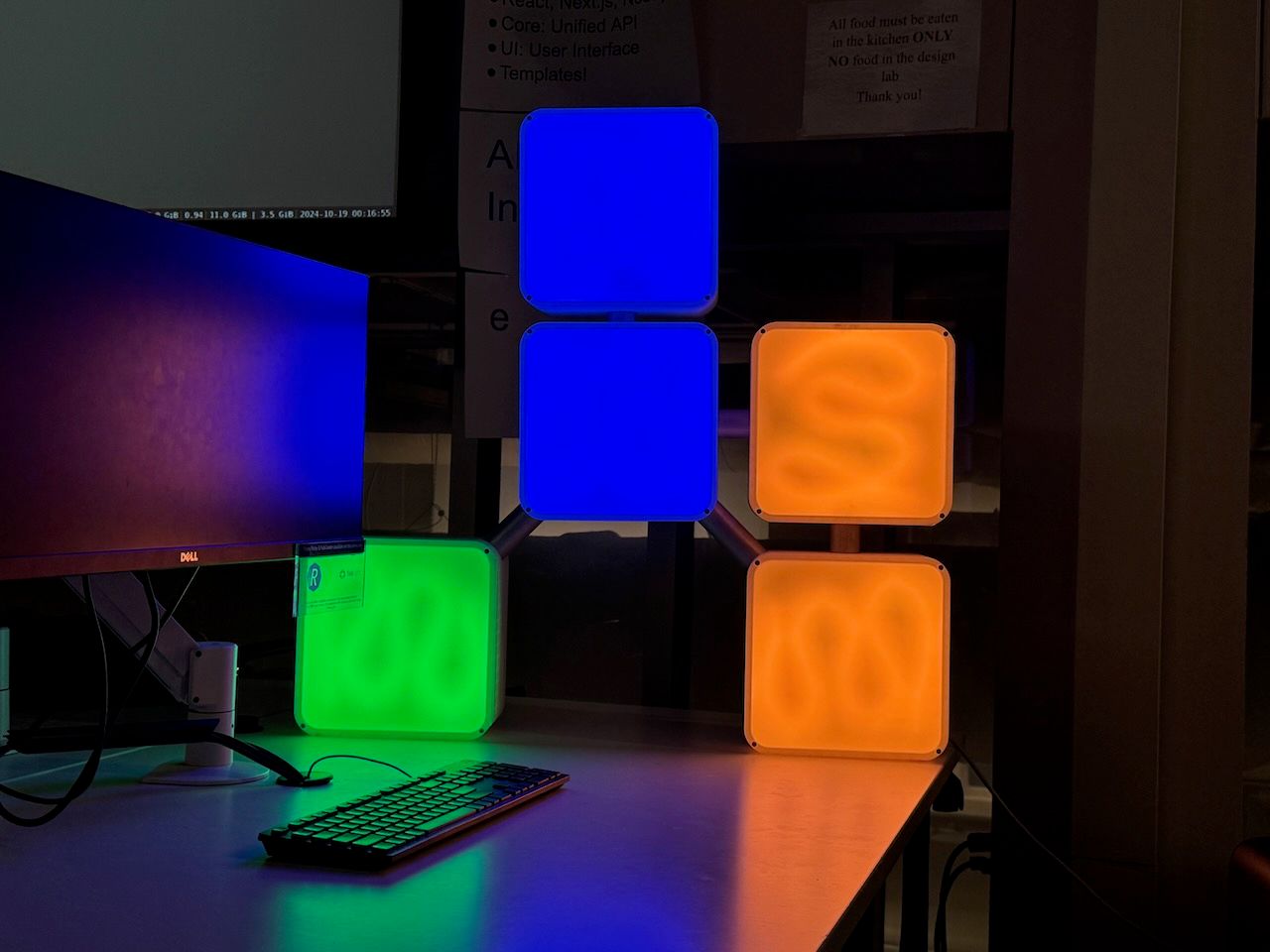
The Sign is a meter-tall Conway glider (which is the Purdue Hackers logo), whose blocks light up according to the color representation of the current time. The Sign shines out from the windows of our makerspace, the Bechtel Center, every Friday night, telling the world when Hack Night is happening. It’s the physical embodiment of the spirit of Purdue Hackers: make something amazing with help from your friends and show it to the world.
The Sign is made of PLA, wood, metal, acrylic, and silicon. It took a year and a half to build and is the fruit of the effort of around ten people. It may look relatively simple, but there is a world of complexity hidden beneath the acrylic paneling and shining LEDs.
I: Spark
April 2023: Hack Nights 2.6 & 2.7
It all started near the end of April 2023 at Hack Night 2.6. A group of Hack Night attendees got together and started brainstorming cool hardware projects that we could pursue. A bunch of cool ideas came out of that session, including a flag, an update to Lightning Time, and other fun projects. The big project of the night, though, was a massive sign of our logo. We envisioned a shining monument to Purdue Hackers, with massive LED panels that we could stick in the window of our venue to show the world that Hack Night was happening.
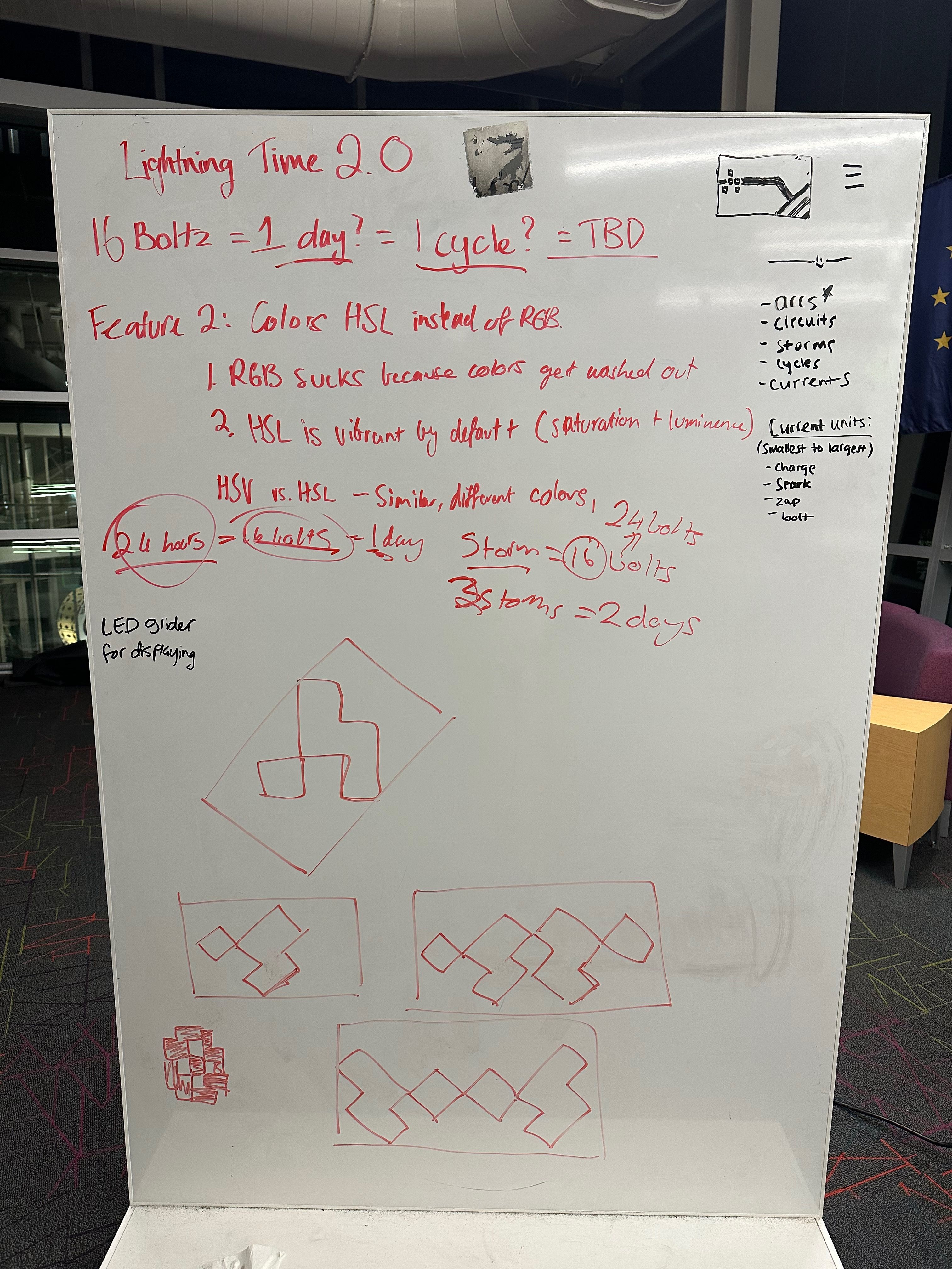
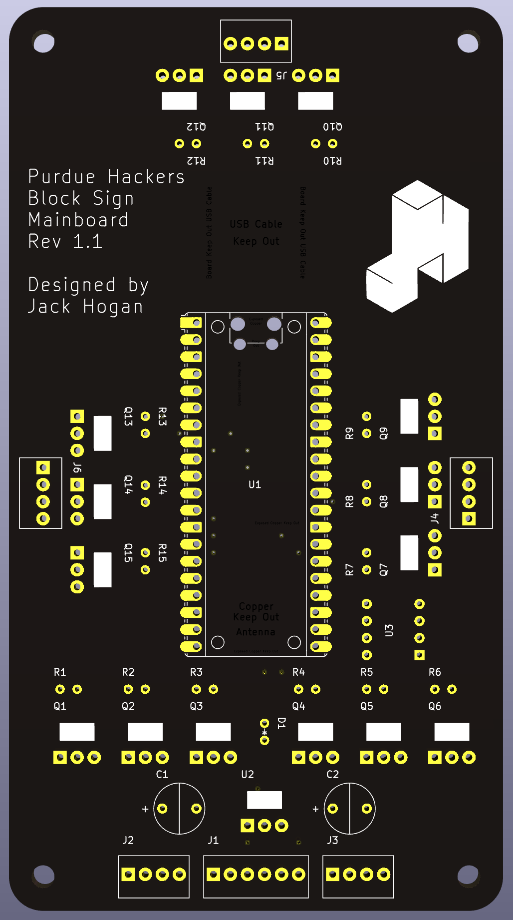
The day after, I started work on the custom PCB that would power the Sign, and another attendee started working on a miniature 3D model of the Sign, which would be scaled up in the end.

While I didn’t initially expect to, I ended up taking a leading position on this project. I thought it would be good to have a project of my own that others at Purdue Hackers could help with, so off I went. I made up a parts list, got a budget to work with of about $200, and ordered the necessary electronic components.
II: Rise
April - November 2023
Once everyone got back from summer break in August 2023, work resumed on the Sign almost instantly. I started work on the CAD for the project, and I did the finishing touches on the PCB I made a few months ago. After a few Hack Nights, we finally got around to ordering the parts. We agreed upon a reasonable $200 floating budget, and I threw together a cart. This penchant for just going for new purchases would continue to bite us in terms of our budget, but at the time everything was going great.
It didn’t take too long for me to get a basic CAD together. We gave an estimated timeline of six-ish months to complete the entire project, hardware and software, so we could start showing it off to prospective members as soon as possible. In fact, since this was our first hardware initiative, we expected to fund many more similar projects like this so other Hackers could get into the physical space just like me. Unfortunately, none of us were very experienced with hardware design at the time, so we had no idea how wrong we were.
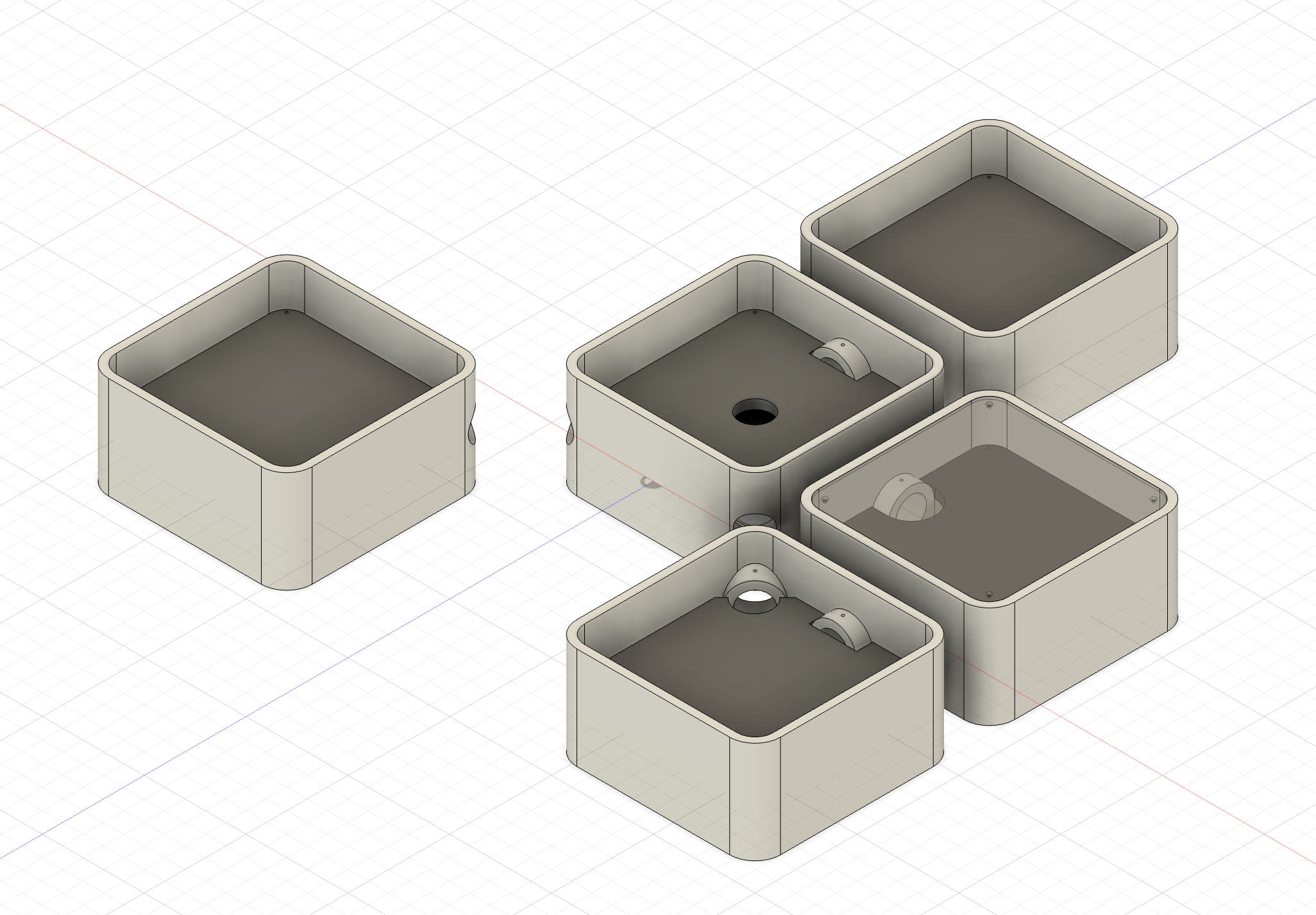
There was some debate over what the Sign should be made out of. Some suggested wood, others sheet metal. We decided that 3D printing would be the easiest way to get the necessary contours without having to deal with advanced manufacturing techniques that could drive us over time or budget. This resulted in us getting four reels of filament, totaling $84.96. This wasn’t even the most expensive part of the (initial) purchase order of the Sign: the LED light strips cost $99. We knew that a $200 was an optimistic target, but with just these two purchases we had blown that budget. We decided to expand the budget to $400 at this point.
Soon after, the PCBs came in. They looked amazing! We were super excited to get everything soldered to it once the rest of the parts came in. I started working on the firmware for the Sign around this point, and while it was a challenge working without many of the creature comforts I was used to within the context of an operating system, I made an initial prototype. At this point we thought we would have a fully-working Sign in September, at the latest October.
III: Fall
December 2023 - February 2024
Soon enough, the parts that I’d ordered arrived and we got our first look at the electronics. Everything looked great at first glance! Everything we needed was there, and I was even able to source some extra parts from my supply so we could save some cash. We were over budget by about $70, but it was fine, right? This was the big expense out of the way. This semester, Hazel, a computer engineer, had started coming to Hack Night, and she had taken some interest in the Sign project. We decided to do the PCB assembly together as a fun project, and her experience in the field would be very helpful regardless.
The second we set up our soldering station for the PCB, we immediately realized two problems, one obvious but fixable, the other more discrete but possibly deadly. First, none of the holes were sized correctly, and some of them were in a completely incorrect location. This was disheartening, but we could work around it by bending leads, making what we called ballerina transistors
to get around this issue.
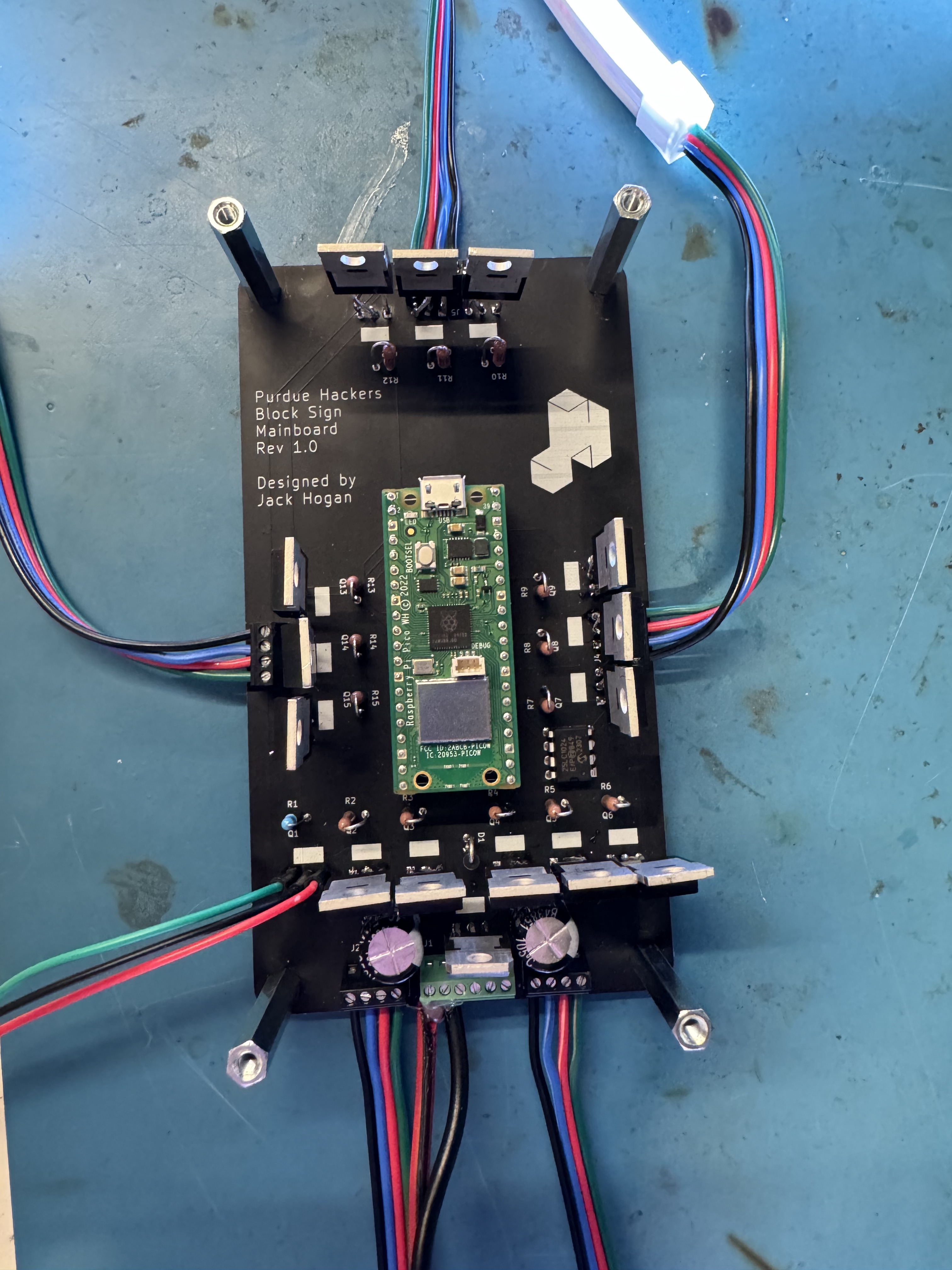
ballerina transistorsin question.
The second problem took Hazel some time to notice, but when she did, it signed this initial board’s death warrant: the traces, or copper paths on the PCB that relays signals between components, were woefully thin for the power we were gonna push through them. We had plans to push around 60 watts of power on traces designed to take about 5 to 10 watts. Oops. This was such an under-spec that it was very possible that the board could catch on fire. Needless to say, we had to rethink some things.
One night I was out at dinner with some friends, one of whom was Caleb, a mechanical engineer. I was talking about the Sign, and Caleb asked to see the CAD out of curiosity. I pulled it up, and he immediately said, where’s your timeline, your joints, your constraints?
I responded, what do you mean?
He gave me a look that I knew meant one thing: I had made more than a few mistakes. Luckily I hadn’t sent off the CAD to be cut and printed yet, so it was really good that he had caught these issues early. Soon after this, I made a real effort to figure out a bill of materials for the structure of the Sign. Unfortunately, I had completely underestimated the costs, and we were gonna end up with the Sign costing around $700 in total, 3.5 times our original budget.
Even after these fixes, I failed to account for the tolerance of the 3D printing, and therefore all of the holes for the connections between the blocks were too small, forcing me to sand the holes for hours to get the pipes to barely fit.
At this point I needed a break, which I would get since there was a lot of fixing to be done.
IV: Rebirth
March - October 2024
After a few months of work things were starting to look up. We had the pipes connecting the blocks together, and the new PCB was delivered. We attached the new and improved components and the Sign came to life!
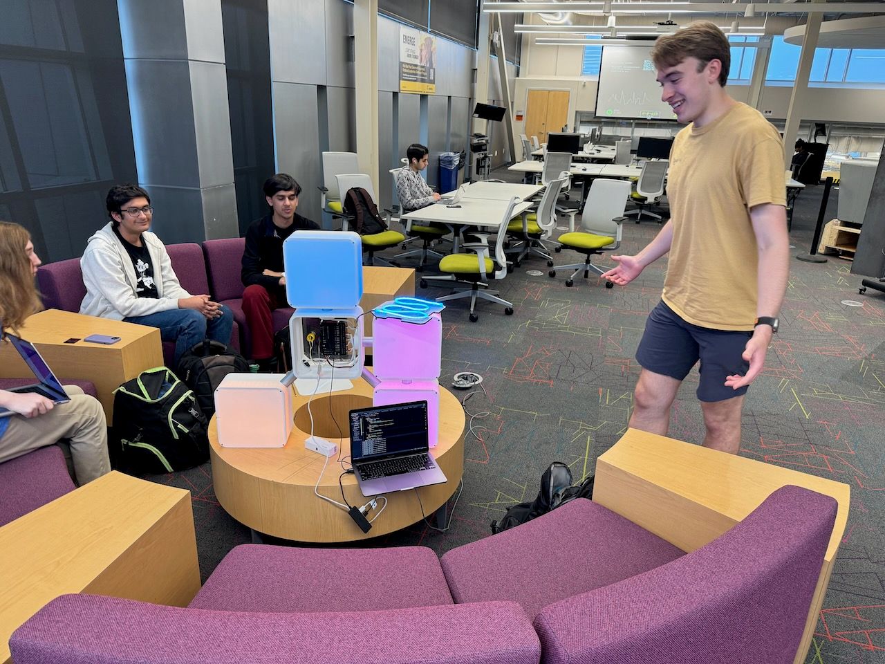
As an aside, by this point, two people who had helped print the component blocks, Tommy and Tejas, had even made a miniature version of the Sign to show how easy
it was to get a working product. It was fun, working, but also one fifth the height of the actual thing.
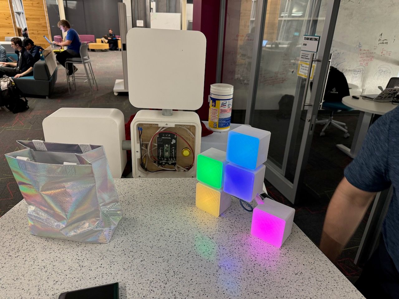
I thought I was gonna catch up with them and ship the Sign very soon after. However, things started to break down. I had issues with the EEPROM that is planned to store configuration settings for the Sign. This took a while to debug, but ended up just being a slight timing issue that I was able to fix with one line of code. The bigger problem was that the Pi Pico had no support for WPA2-Enterprise.
Purdue, like many other organizations, wants to know who’s on their network and who owns what device. A reasonable ask, but an absolute nightmare for me. There wasn’t even a function to call to get the Pico to connect to Purdue’s network, PAL3.0. I did some digging and found a network, PAL-Gadgets, that used traditional WAP2 security. Great! Slight problem: the network requires emailing people to get devices on it, each device is registered per MAC address, and worst of all, the network only works in certain rooms around campus. I decided that we could make it work, so I went through a maze of emails before eventually getting access to the network. I ran my code to synchronize with the internet, and… nothing. Sometimes my network packets were able to get through to the open internet, but the more I tried the worse that chance got. I went through all five stages of grief trying to get this working. I even considered ordering a second Pi Pico, thinking it may be a manufacturing issue. All of this took months and significantly delayed the Sign.
After way too long trying every which way to get the Pico online, I made a tough decision: I abandoned the Pico. This resulted in me having to completely rewrite my code and find a suitable replacement controller. After some research I settled on the ESP32-S3. I had used it in a similar project and it worked well enough. I designed a quick board to convert the Pico slot to one that could fit an ESP32-S3 and ordered it.
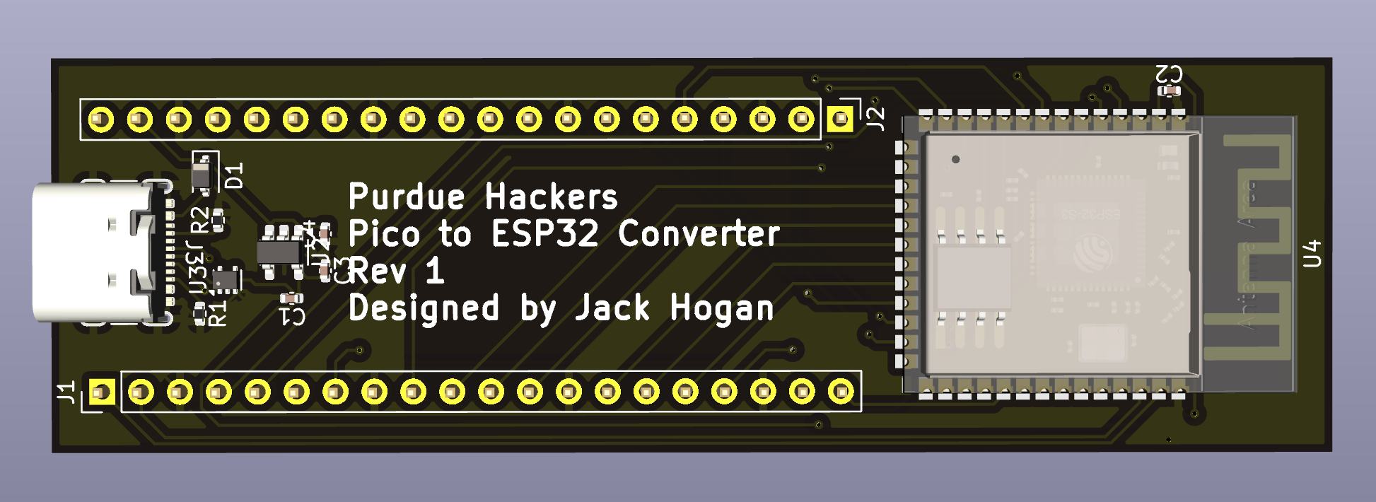
Soon enough it came in and Hazel assembled it. I got to work writing some new code for the Sign, and things went very well for the first couple of days! I even got the ESP connecting to PAL3.0, something that made my life much easier, allowing the Sign to connect to Wi-Fi anywhere on campus. However, I soon ran into a problem: the Sign’s LEDs require the use of pulse width modulation, or PWM, to change their brightness and make a full color gamut. The ESP32-S3 doesn’t have enough PWM channels for all of the LEDs. This meant that I couldn’t control the Sign and make it display every color I wanted to. In fact, no more than about 10! Hazel and I brainstormed, trying to implement PWM in software but to no avail. This setback was particularly frustrating since we all felt like we were so close to the finish line.
After spending some time on other projects, I went back to the drawing board. Some further research revealed that the ESP32 original did have enough PWM channels for the Sign. This was good, but the ESP32 lacked the same connection system as the ESP32-S3, meaning I would need additional interfacing circuitry to make it work. I added the necessary things, ordered it, and it arrived soon after.
When I first attempted to power on the board, it didn’t boot. Dread started to surround me. What had I done wrong this time? After further investigation, Espressif, the makers of the ESP32 series, use a special communication chip for the ESP32 with special connections that I didn’t realize were necessary. A reasonable mistake, but still infuriating. The fix this time was much simpler: solder a button onto two of the ESP32’s pins to bypass the need for the special communication chip, making it possible for the chip to boot and accept new firmware. This would cause programming the chip to be a pain, since the button had to be held down for a very specific length of time to get the ESP32 into a mode that would accept code, but it worked.
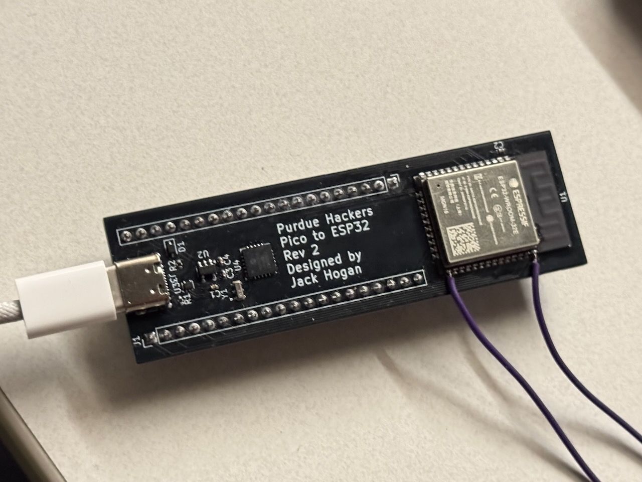
I was able to reuse most of the code from the ESP32-S3 to the ESP32, so development went relatively quickly after this. I implemented the PWM code, spent a long time getting self-updating firmware working through GitHub CI, and cleaned up my code. After 548 days of blood, sweat, and tears at around 15:30 on October 13, 2024, the Sign version 1.0 finally shipped!
V: Future
October 2024 - ∞
The future is bright for the Sign. There are many possibilities for new software, such as integration with ID or the dashboard and custom lighting patterns made with a full animation editor. The button on the back of the Sign is yet to be assigned any purpose, so it could be used for anything from switching profiles to ringing a bell somewhere. There are still some issues: the EEPROM is not accessible due to an issue with the ESP32 conversion board and the boot button is an annoyance that should be fixed in the next revision of the board.
Overall, this project has taught me so much about project management, budgeting, collaboration and teamwork, but most potently, getting up when you’re knocked down. I can’t count how many times that happened, but if I didn’t manage to get up after each and every time that happened, I wouldn’t have written this blog post. In the end, it was all worth it to finally see the Sign lighting up the night.
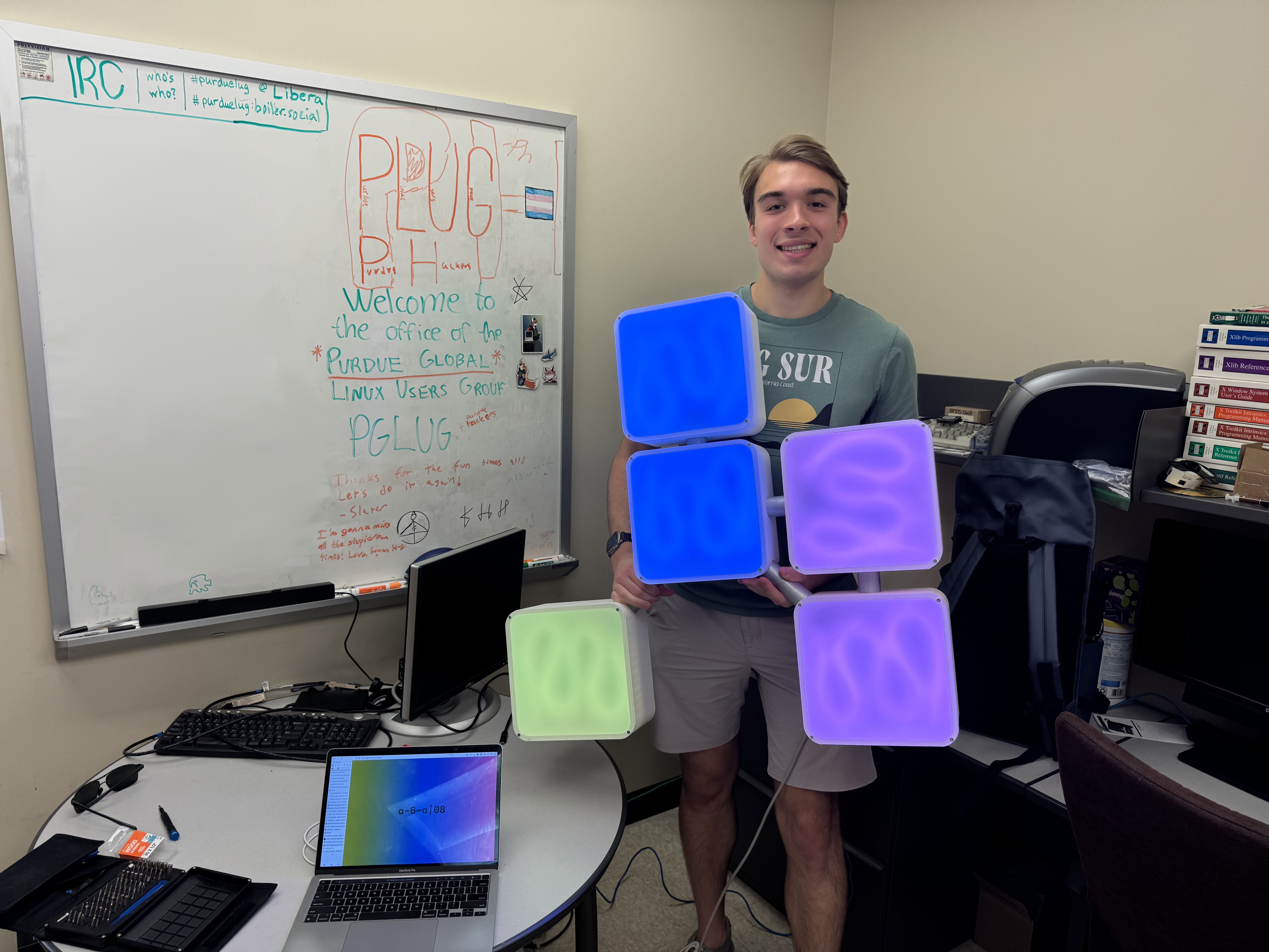
P.S. Every part of the Sign is open source!